Installation: DS Lite
Midify Installation: DS Lite
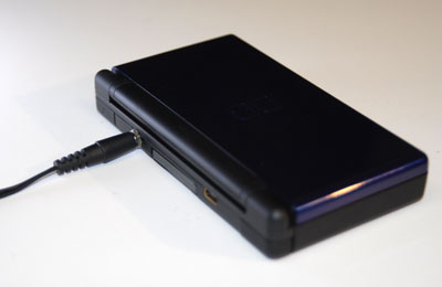
Here is a step-by-step example of how to install Midify into a Nintendo DS Lite.
What you need
- Game Boy Advance SP
- Midify + Accessories
- Tri-Wing Screwdriver
- Small Phillips Screwdriver
- Low-Wattage Soldering Iron with Fine Tip
- Solder
- Wire Cutters
- Wire Strippers for 30AWG Wire
- Utility Knife and/or Dremel Tool
- Drill and drill bits
- Electrical Tape
- Needle-nose Pliers
Disassemble the DS Lite
With the DS Lite upside-down, remove the stylus and the Slot-2 plug. Use a Phillips screwdriver to remove the battery cover.
Remove the battery.
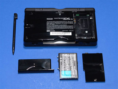
Use a knife to pry off the two rubber feet (there are screws underneath).
Remove the screws that hold the back of the case on. You will need a Phillips and a tri-wing screwdriver.

Lift the back half of the case off of the DS. The bottom edge may stick a little, but it just snaps on and off.
Remove the L and R buttons, being careful not to lose the pins and small springs that are attached to them.
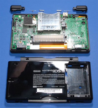
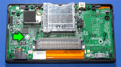
Remove the remaining screw that is holding the PCB in place.
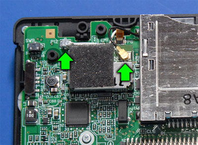
Disconnect the black antenna wire from the WiFi module and pull it out from under the Slot-1 assembly.
Disconnect the white microphone wire from the board.
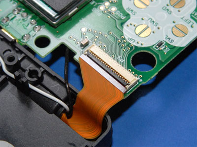
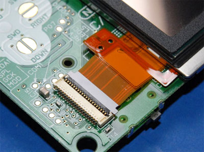
Disconnect the small ribbon cable that runs the touch screen by flipping the black part of the connector up and sliding the ribbon out.
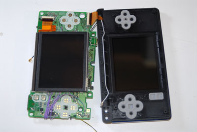
Flip the board and the bottom LCD up and out of the case.
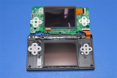
Disconnect the two ribbon cable connectors that go to the screens by flipping the dark-gray part of the connectors up and sliding the ribbon out.
Place the touch screen back in the top half of the case and set them aside.
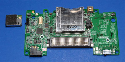
Remove the WiFi module from the rest of the board by pulling straight up on it.
Install the Midify Board
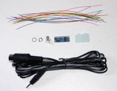
Gather all the parts that came with your MIdify kit.
Melt a blob of solder onto each pad of the Midify board. This will make it easier to attach wires later.
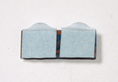
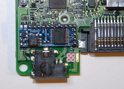
Use the double-sided tape to stick the Midify board to the DS Lite board in the position shown.
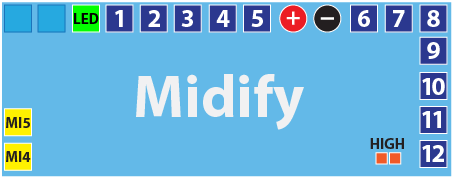
The labels on the Midify board are pretty hard to read, so here’s a diagram:
Solder two wires to MI4 and MI5.
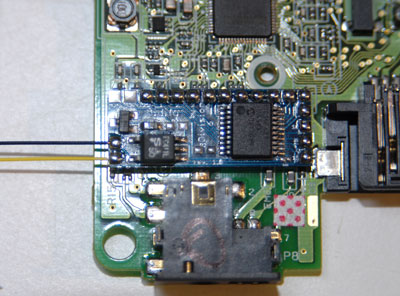
Bend them under the board as shown. This will keep them out of the way while you are connecting the rest of the wires.
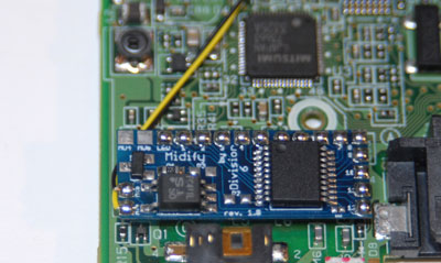
Solder a wire to the LED pad.
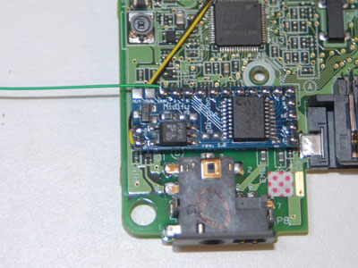
Bend the wire around the edge of the board. Solder the other end to the pad marked “Green”. Route the wire as shown.

Now it’s time to start connecting wires from the output pads to the DS buttons. The exact order in which you do this will depend on what you are using your Midified DS for, but remember that you can always reconfigure the keymapping later. Here’s a suggested connection scheme:
|
Midify Output
|
DS Connection
|
Button Name
|
|---|---|---|
|
1
|
P06
|
Up
|
|
2
|
P07
|
Down
|
|
3
|
P05
|
Left
|
|
4
|
P04
|
Right
|
|
5
|
P03
|
Start
|
|
6
|
P02
|
Select
|
|
7
|
P00
|
A
|
|
8
|
P01
|
B
|
|
9
|
R00
|
X
|
|
10
|
R01
|
Y
|
|
11
|
P09
|
L
|
|
12
|
P08
|
R
|
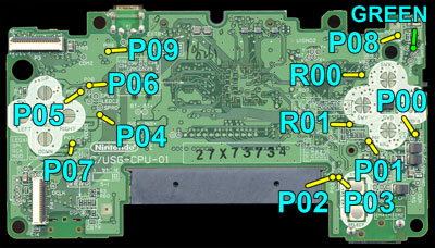
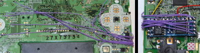
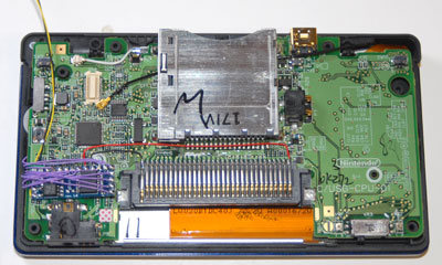
Here are the locations of all the button connections on the DS Lite board:
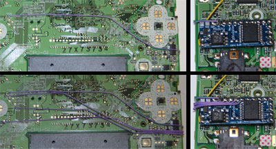
Hook up the output wires one-by-one, going in order across the top of the Midify board. Make sure you route the wires in such a way that they avoid tall components, screw holes, button pads and white areas.
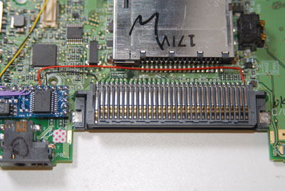
When you get to the two power supply connections, connect them as follows:
|
Midify Pad
|
Cartridge Connector Pin
|
|---|---|
|
+
|
1
|
|
–
|
32
|
Continue connecting the remaining input wires.
Modify the Case
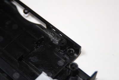
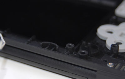
Once you have the Midify board all connected up to the DS Lite PCB it’s time to do some modifications to the case. First we’ll free up some room for the Midify board. Use a Phillips screwdriver to remove the three screws that hold the stylus channel in place.
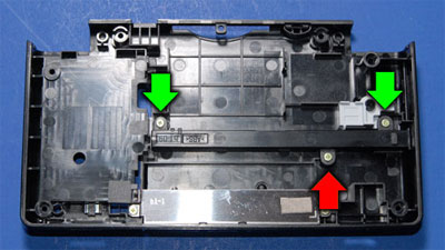
Use a utility knife or wire cutters to remove the middle screw tab (the one with the red arrow).
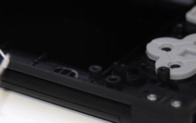
Replace the stylus channel, only screwing down the two tabs that you didn’t clip.
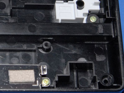
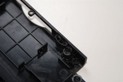
Now we need to make a place for the jack. Start by using a knife or Dremel to remove the crescent-shaped bit of plastic that sits behind the lanyard holes in the case.
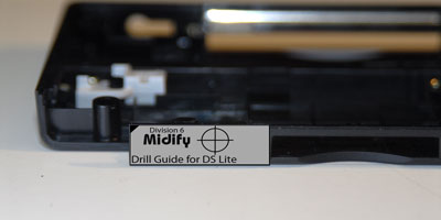
Drill a 7/32″ hole in the case. You can download this handy template to get the position right:

When you print it out make sure you disable any kind of scaling / reduction; it must print actual size.
Cut the template out and stick it to the DS case as shown, with the marked corner lining up with the corner of the shoulder button hole and the top and left edges flush with the case edges.
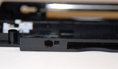
Note: The jack hole overlaps one of the existing lanyard holes which could make it a bit difficult to drill. You may find it easier to use a dremel to enlarge the lanyard hole until it is the correct size and shape.
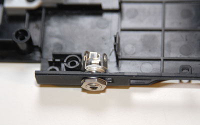
Test-fit the jack. Note that it should be oriented so that the gap in the solder tabs is facing up. This will prevent it from pressing on the DS PCB after everything is put back together. Also note that the hole is just a little bigger than it needs to be. This allows for some wiggle room in positioning the jack.
Remove the jack from the case and set it aside.
Set the bottom half of the case aside and get the top. Use a knife to trim the crescent-shaped bit of plastic so that it is flush with the edge of the case (this part doesn’t need to be completely removed; flat is fine).
Reassemble the DS Lite
Start by placing the PCB, button-side up, next to the top half of the case. Reconnect the ribbon cable for the top screen by sliding it back into the connector and flipping the latch back down.
Lay the bottom touch screen on the PCB and connect its ribbon cable.
Note: Make sure that the ribbon cables are inserted all the way into the connectors before you latch them or the system will not boot.
Flip the board / LCD combination over and let everything settle back into position in the case. You will now feel some wobbliness of the board because of all the wires that are now underneath it, but you shouldn’t have to press very hard to get the board to lay flat.
Replace the screw near the Midify board that holds the PCB in place.
Reconnect the small ribbon cable by sliding it into its connector and flipping the latch back down.
Reconnect the white microphone wire to the PCB.
Thread the black antenna wire back under the Slot-1 assembly.
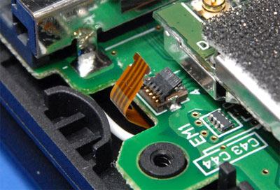
Cut a small rectangle of electrical tape and stick it on top of the small ribbon connector. The MIDI jack shouldn’t normally make contact with this but the tape will prevent shorts in case the jack gets rotated or wiggled too much.

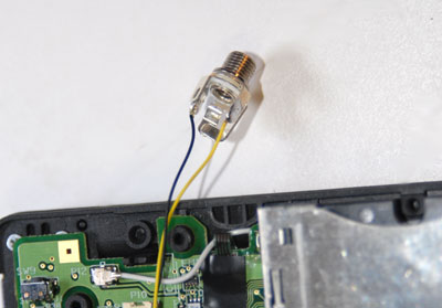
Cut the two jack wires to the length shown:

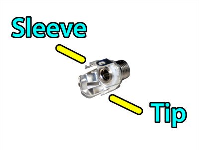
Solder the two wires to the jack. Make sure you get the correct polarity.
|
Midify Input
|
Jack Connection
|
|---|---|
|
MI4
|
Tip
|
|
MI5
|
Sleeve
|
Place the bottom half of the case next to the top half.
Install the jack into the hole you made earlier. Make sure that the gap in the solder tabs is facing up. First slide the washer on then tighten the nut in place. You can a 9/32″ socket or pliers if you’re careful.
Reinstall the WiFi module.
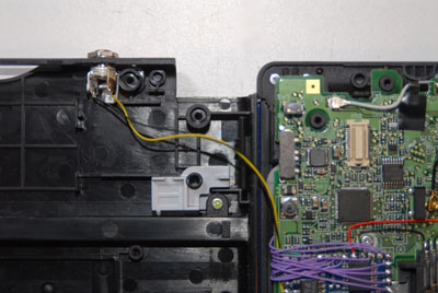
Reconnect the black antenna wire. Make sure that the wire points towards the Slot-1 assembly instead of the back of the DS so that there is room for the MIDI jack.
Reinstall the L and R buttons along with their pins and springs.
Flip the bottom of the case over and back into position, routing the jack wires around the WiFi module as you go. You may need to wiggle the Midify board around a bit to get it to fit in the open space in the case. If it still won’t go all the way on make sure the caps for the volume and power sliders are lining up with their repective switch/pot.
Also look at the back of the jack as you snap the case back together to make sure it doesn’t look like it’s interfering with anything.
Replace all the screws in the bottom of the DS.
Replace the two rubber feet.
Replace the battery.
Reinstall the battery cover.
Replace the stylus and the Slot-2 plug.
Now you should be ready to try things out!
Test Things Out
Connect the included MIDI cable from your DS Lite to a MIDI keyboard.
Insert your favorite cartridge.
Power on the keyboard and the DS Lite.
You should now be able to control your DS Lite by pressing keys on the keyboard. You may wish to change some of Midify’s configuration settings to make it low-note priority, polyphonic, etc.
Have fun!