Installation: Game Boy Color
GBAccelerator GBC Installation: Game Boy Color
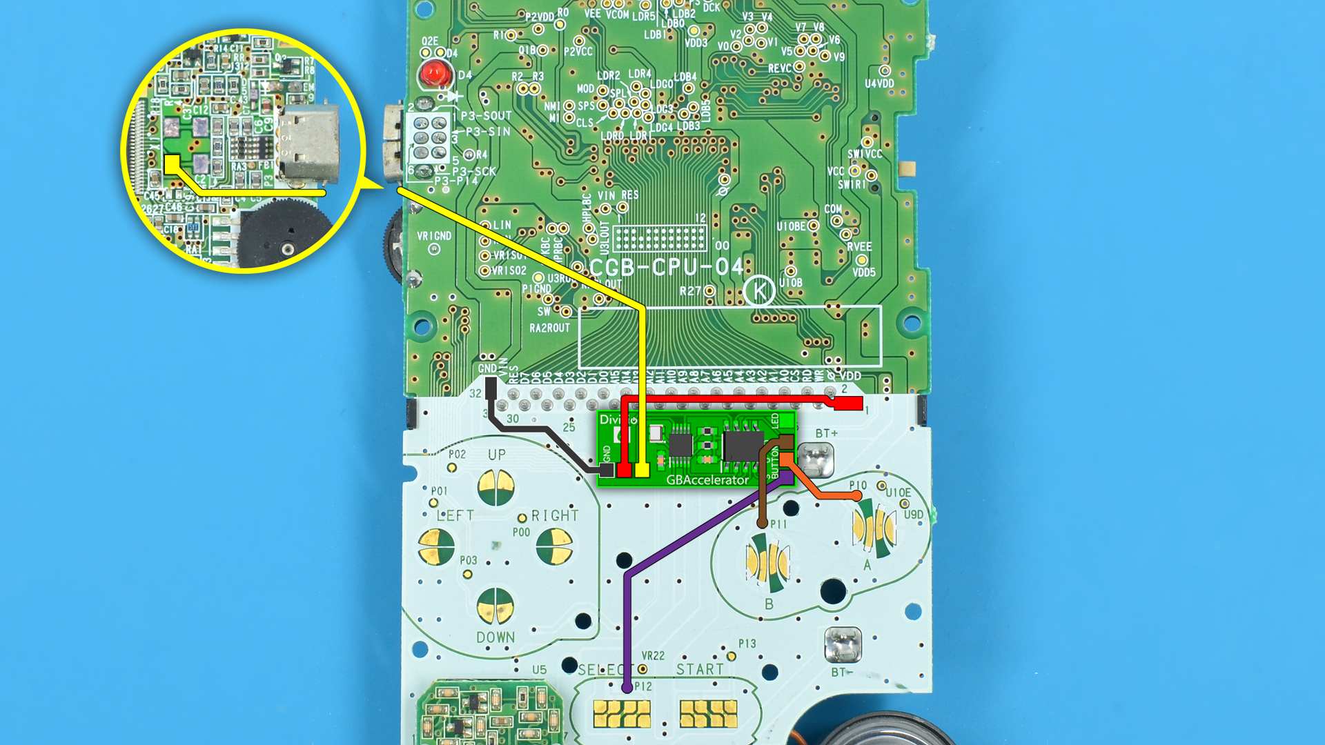
- Disassemble your Game Boy Color
- Remove crystal X1
- Place the GBAccelerator on the PCB as shown in the diagram
- Make connections as shown in the diagram
- Reassemble your GBC
|
GBAccelerator GBC Connections
|
|
|---|---|
| GND | Cartridge Connector Pin 32 (GND) |
| V+ | Cartridge Connector Pin 1 (VDD) |
| CLK | X1 Bottom Left Pin |
| LED | Q2E |
| BUTTON (S) | P12 |
| BUTTON (U) | P10 |
| BUTTON (D) | P11 |
Installation Tips
- Use low-wattage, fine-tipped soldering iron
- Use flux or rosin-core solder
- Don’t hold the iron on the GBAccelerator or the GBC board too long as you may lift the solder pad
- Solid 30-gauge wire is recommended
- Follow wire routing indicated in diagram so wires don’t cross button pads, screw holes, or tall components
- Cut off excess wire length
- If using normal control mode, the three button connections on the GBAccelerator are interchangeable; it does not matter which one goes to which button. If you wish to use up/down control mode, make sure the correct button inputs (Select, Up, Down) are connected to the desired GBC buttons
- If alternate button assignments are desired, see button signal list for available connection points
|
Button Signal List
|
|
|---|---|
|
P00- Right |
P10- A
P11- B P12- Select P13- Start |