Installation: Game Boy
GBAccelerator GB Installation: Game Boy
- Disassemble your Game Boy
- Remove the CPU board from the case
- Remove crystal X1
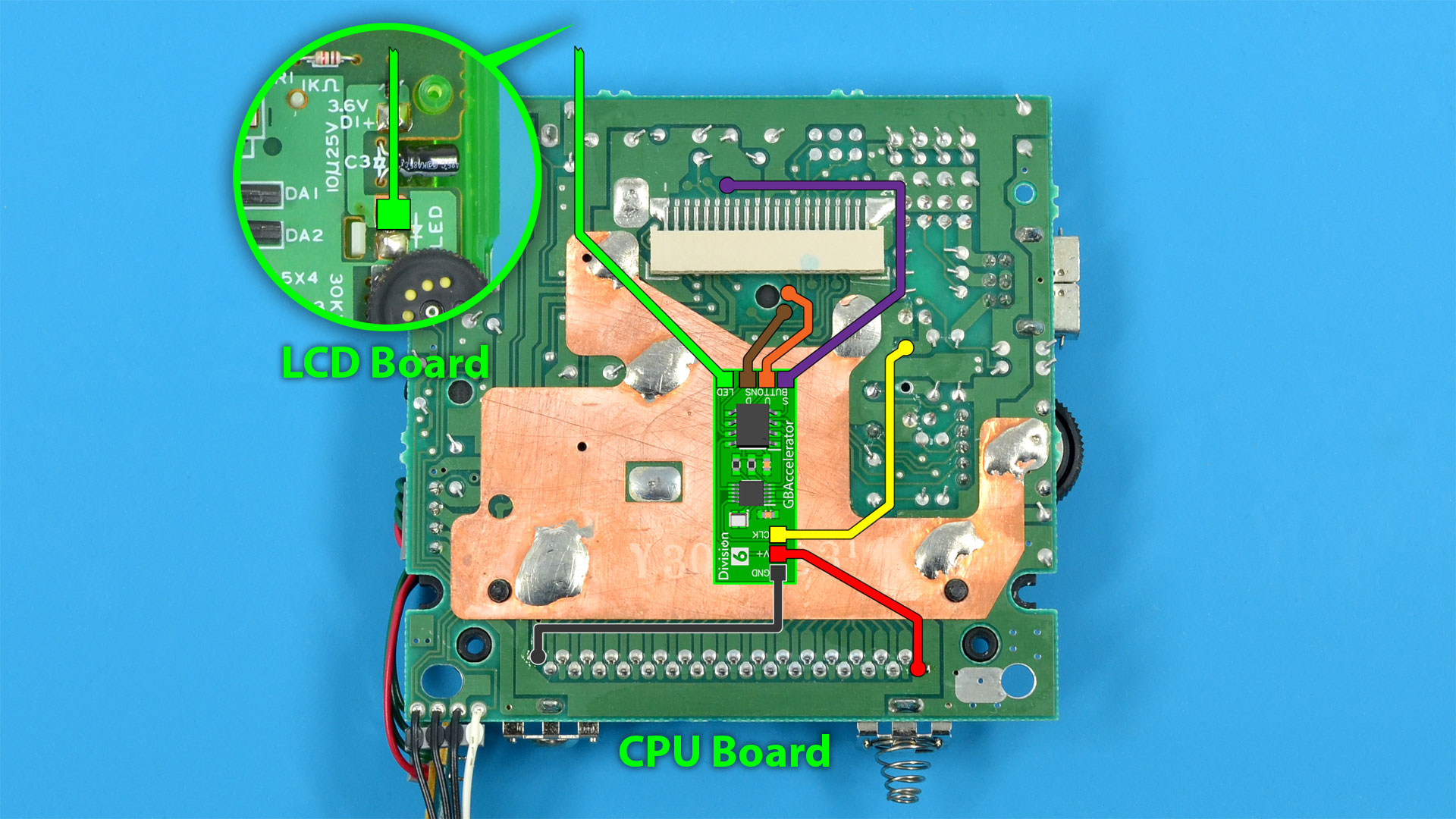
- Place the GBAccelerator on the PCB as shown in the diagram
- Make connections as shown in the diagram
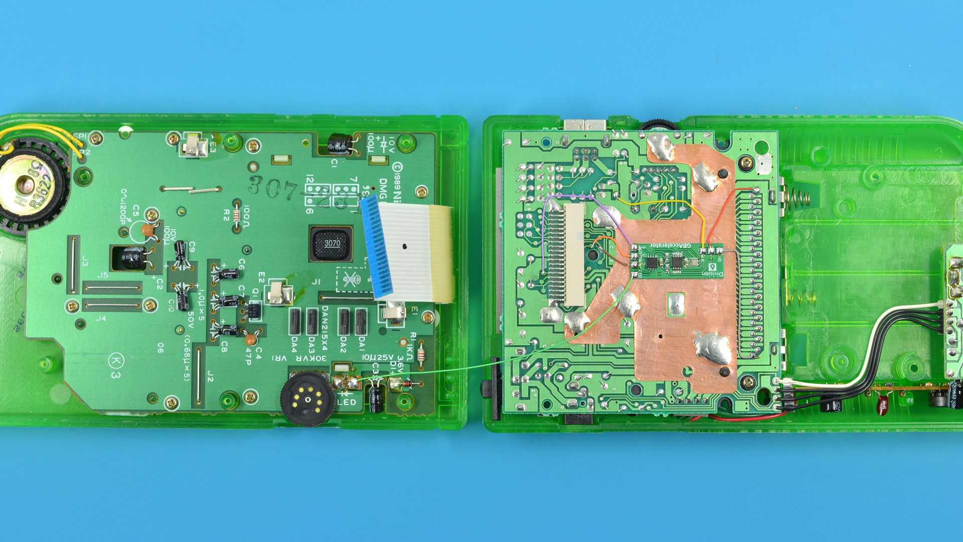
- Note: The LED wire will travel to the LCD board in the other half of the case
- Reassemble your Game Boy
|
GBAccelerator GB Connections
|
|
|---|---|
| GND | Cartridge Connector Pin 32 |
| V+ | Cartridge Connector Pin 1 |
| CLK | X1 Top Pin |
| LED | LED Anode (+) Pin |
| BUTTON (S) | LCD Board Ribbon Cable Connector Pin 7 |
| BUTTON (U) | LCD Board Ribbon Cable Connector Pin 8 |
| BUTTON (D) | LCD Board Ribbon Cable Connector Pin 9 |
Installation Tips
- Use low-wattage, fine-tipped soldering iron
- Use flux or rosin-core solder
- Don’t hold the iron on the GBAccelerator or the Game Boy board too long as you may lift the solder pad
- Solid 30-gauge wire is recommended
- Follow wire routing indicated in diagram so wires don’t cross button pads, screw holes, or tall components
- Cut off excess wire length
- Some of the solder points may be covered with green solder mask. Use a blade to carefully scrape away the mask without damaging the copper pad underneath.
- When reassembling the two case halves, make sure the LED wire doesn’t get pinched or interfere with anything