Installation: Game Boy SP
GBAccelerator GBA Installation: Game Boy SP
click here for a detailed walkthrough
- Disassemble your Game Boy Advance SP
- Desolder and remove crystal X1
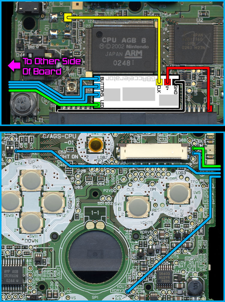
- Place the GBAccelerator on the PCB between the ARM processor and the cartridge connector as shown in diagram (click diagram to enlarge)
- Make connections as shown in diagram
- Reassemble your GBA-SP
|
GBAccelerator Connections
|
|
| GND | Cartridge Connector Pin 32 |
| V+ | Cartridge Connector Pin 1 |
| CLK | CK1 (solder pad where xtal used to be) |
| LED | DL2A |
| BUTTON | TP2 |
| BUTTON | TP8 |
| BUTTON | TP9 |
Installation Tips
- Do not take the GBA-SP screen apart; it is only necessary to disassemble the base
- You may need to use some electrical tape between the GBAccelerator and the cartridge connector to prevent accidental contact
- Use low-wattage, fine-tipped soldering iron
- Use flux or rosin-core solder
- Don’t hold the iron on the GBAccelerator or the GBA board too long as you may lift the solder pad
- Solid 30-gauge wire is recommended
- Follow wire routing indicated in diagram so wires don’t cross white areas, screw holes, or tall components
- Cut off excess wire length
- The three button connections on the GBAccelerator are interchangeable; it does not matter which one goes to which button
- If alternate button assignments are desired, see button signal list for available connection points
- You may need to trim some of the plastic standoffs from the back cover of the GBA-SP if the cover does not seat properly upon reassembly
|
Button Signal List
|
|
|---|---|
|
TP0- A
TP1- B TP2- Select TP3- Start TP4- Right |
TP5- Left
TP6- Up TP7- Down TP8- R TP9- L |