Installation: DS
GBAccelerator DS Installation: DS
Click here for a detailed walkthrough
- Completely disassemble the bottom half of the DS
- Desolder the four metal tabs holding the DS game cartridge connector to the PCB. Lift the connector up (the pins will still be connected to the PCB and will act like a hinge)
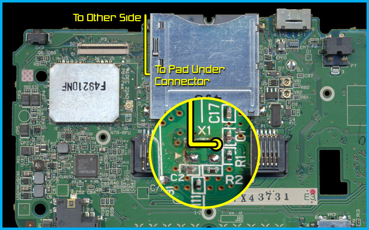
- Desolder and remove crystal X1
- Solder a wire to the crystal solder pad indicated in the wiring diagram (see yellow circle)
- Re-solder the cartridge connector to the PCB
- Flip the PCB over. Use double-sided tape to stick the GBAccelerator DS chip to the DS board in the position indicated in the diagram
- Connect the remaining wires as indicated in the diagram
- Reassemble the DS

| GBAccelerator DS Connections | |
|---|---|
| GND | BT- |
| V+ | VDD3.3 |
| CLK | Solder pad where xtal used to be |
| LED | Green |
| BUTTON | P02 |
| BUTTON | P08 |
| BUTTON | P09 |
Installation Tips:
- Do not take apart the top half of the DS; it is only necessary to disassemble the bottom half
- Use low-wattage, fine-tipped soldering iron
- Use flux or rosin-core solder
- Don’t hold the iron on the GBAccelerator or the DS board too long as you could lift the solder pad
- 30AWG wire is recommended
- Follow the diagrams for chip placement and wire routing so that they don’t interfere with buttons, standoffs, tall components, etc. It will make reassembling your DS much easier
- Cut off excess wire length.
- The three button connections on the GBAccelerator DS are interchangeable; it does not matter which one goes to which button
- If alternate button assignments are desired, see button signal list for available connection points
| Button Signal List | |
|---|---|
|
P00- A
P01- B P02- Select P03- Start P04- Right P05– Left |
P06- Up
P07- Down P08- R P09- L R00– X R01– Y |